
GE Analytical Instruments, Inc. ©2005H Page 5 of 16 DIN 30001 Rev. E
TOC,FLOW SWITCH UPGRADE 2.12CBI
5.2.9. Select each consumable, press Enter. Write the information on
the Printout or the Constants Record Form. Record date and
percent left for the OXIDIZER. Record the percent left for the
LAMP, PUMP TUBING and ACID.
5.2.10. REAGENT FLUSH is not a consumable to record.
5.2.11. Print or record Errors and Warnings if desired.
5.2.12. Data on the Ram Card will not be erased or affected in any way
upon performing this procedure.
5.3. Replace the EPROM chip (IC chip).
CAUTION:
Prior to performing the following instructions it is essential, to be grounded
according to established procedures. Failure to be properly grounded will
result in damage to the EPROM Chip and void the warranty.
5.3.1. Turn off the analyzer power and disconnect the power cord.
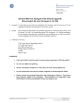
5.3.2. Lift the analyzer cover and locate the PC electronics board, refer to
Figure Six.
5.3.3. Depending on the type of chip holder in the analyzer, different
techniques are required to replace the existing EPROM with the EPROM
labeled 2.12CBI. Facing the analyzer’s front panel, locate the EPROM
socket on the left side of the PC electronics board near the rear of the
analyzer. If the chip socket has a metal lever at the top, it is a Zero
Insertion Force Socket (Step 5.3.4). If the chip socket does not have a
lever, it is a Low Profile Socket (step 5.3.5). Figure Six illustrates the low
profile socket. Use the appropriate instruction to replace the chip.
LOWER TAB
SCREW DRIVER HERE
UPPER TAB
RIGHT INDEX
FINGER HERE
FRONT OF TOC
EPROM
CARRIER
SOCKET
PC BOARD
OTCH
(POWER SUPPLY)
PC BOARD
IC SOCKET
FIGURE SIX: Low Profile Socket Replacement


 England
  Deutschland
  France
  Italia
  Polska
  United Kingdom
  Россия
  Nederland
  España
  Magyarország
  Sverige
  România
  Portugal
  Colombia
  Suomi
Suomi  New Zealand
  Česká republika
  Türkiye
  Danmark
  日本
日本